
***IMPORTANT***
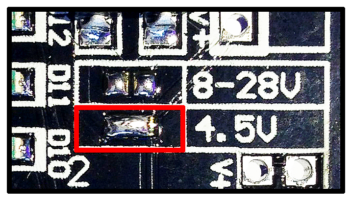
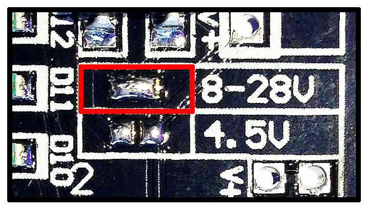
Before you can start using the LED Magician, please select the correct input voltage by shorting the connections labelled "8-28V" or "4.5V".
Before you can start using the LED Magician, please select the correct input voltage by shorting the connections labelled "8-28V" or "4.5V".
LED Magician Installation instructions
- Connect power supply’s negative (-) to terminal labelled “V0”
- Connect power supply’s positive (+) to terminal labelled “V+”
- Connect LED(s) anode (+) to output terminals labbelled “V+”
- Connect LED(s) cathode (-) to output terminals labbelled “1” to “12”
- Control sequences via onboard control buttons.
LED Magician Connection Diagrams
You can connect the positive (+) and negative (-) of your LED(s) from each channel output. (example 1)
Example 1.
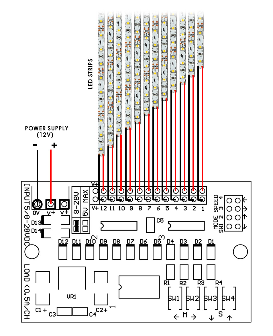
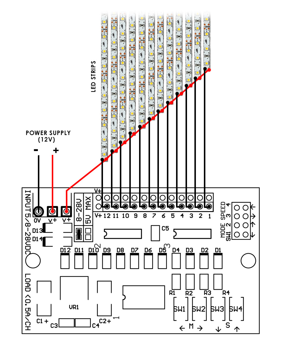
Or you can connect the negative (-) of your LED(s) to the channel output and share the positive output on your LEDs, please see example 2 below. Both methods work the same.
Example 2.
On Board Buttons
Use button 1 & 2 to select blinking sequences. Up to 32 sequences are selectable. Press and hold for 2 seconds to reset to default sequence (Default sequence cycles through all 32 sequences)
Use button 3 & 4 to select speed. Up to 8 speeds are selectable. Press and hold for 2 seconds to reset to default speed.
List of Blinking/Fading Sequences (32 modes)
- LOOP ALL MODES
- COMET
- COMET BACK AND FORTH
- TRAIN
- TRAIN BACK AND FORTH
- BOUNCE
- COLLISION
- SEPARATION
- CENTER BUILD UP FROM LEFT AND RIGHT
- CENTER BUILD UP FROM LEFT AND RIGHT (RANDOM OFF)
- DOOR CLOSING
- SPRING
- CRISS-CROSS (RANDOM OFF)
- CRISS-CROSS (SLOW OFF)
- CENTER BUILD UP FROM LEFT, THEN RIGHT
- CENTER BUILD UP FROM LEFT, THEN RIGHT (RANDOM OFF)
- PENDULUM
- 1 DOT WATER FLOW
- 1 DOT WATCH FLOW BACK AND FORTH
- 2 DOTS WATER FLOW
- 2 DOTS WATER FLOW BACK AND FORTH
- 3 DOTS WATER FLOW
- 3 DOTS WATER FLOW BACK AND FORTH
- 4 DOTS WATER FLOW
- 4 DOTS WATER FLOW BACK AND FORTH
- FADE IN, FADE OUT
- FLASHING (STROBE)
- FLASHING (STROBE) LEFT AND RIGHT
- FLASHING (STROBE) POLICE LIGHT
- ALTERNATE FADE IN AND OUT
- RANDOM ON, RANDOM OFF
- DISCO LIGHTS
Installing external controls
You can wire-out external controls by using the through-holes located at the top right corner of the circuit board.
Using a micro-controller;A "push" of the control buttons are simulated via an "active low" TTL signal from your micro-controller.
The connection should be kept "high" at 5v and a "low" level signal simulates a press of the switch.
Have a question? Find your answers at our "Frequently Asked Questions" page
4 pcs left
VERY LIMITED STOCK!:
"The LED Magician" has been discontinued for quite some time now but we found a small quantity left nicely tucked away in a corner of our warehouse! For those who had sent us multiple emails regarding availability here's the chance to grab them before they are inevitably gone! Just $2.90 flat-rate shipping via registered (trackable) 7-14 days mail to anywhere in the world* and free-shipping within Singapore.